Modelling a cup, drinking glass or bottle seems to be a standard exercise for someone learning 3D, so here’s my attempt at a mug.
Click images for larger view
Lightwave 3D is a two-part program; the Modeler part for constructing model geometry and assigning basic surface characteristics, and Layout for assembling single or separate models into a scene, lighting it appropriately, and animating it if needed. Whether a series of still images for an animation or a single image, Lightwave Layout is responsible for rendering the scene to the final quality, displaying all the lighting, shadows, reflections and surfacing. Lightwave does actually have a third part called Hub for managing data exchange between Modeler and Layout, but Hub generally runs in the background, seldom, if ever, requiring the user’s attention.
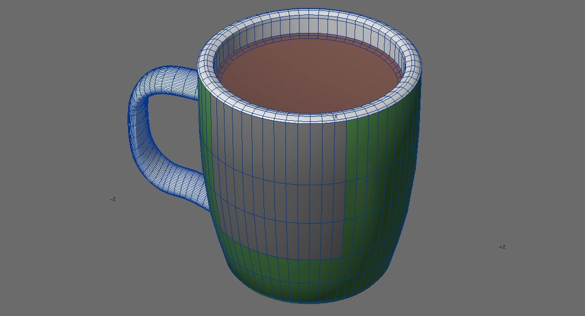
The mug in Lightwave Modeller, seen in Wireframe Shade view. The grey polygons are where the Milo logo image will be placed (one on each side); the brown polygons are where the Milo photo image will be placed. The blue wireframe will not be visible in the final render.
Surface attributes are assigned to the model (in either Lightwave Modeler or Layout); the Milo logo is a TIFF image.
The Milo logo TIFF image and its green background colour values in Photoshop. The green polygons on the outside of the mug were set to the same colour values so that there was a seamless blend between the TIFF image and the Lightwave polygons.
![]()
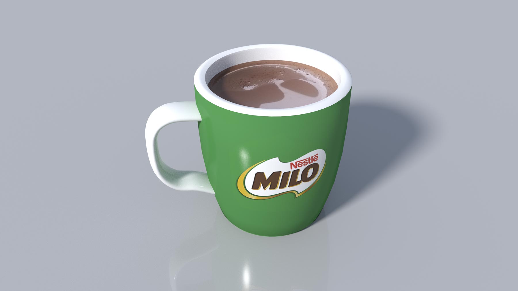
Modeler only provides a basic view of surfacing, basic lighting and shadows; the final quality image has to be rendered in Layout.
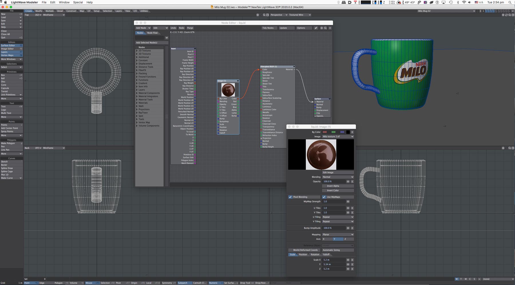
The liquid surface is made from a photo of a real cup of Milo. The photo was colour corrected and generally cleaned-up in Photoshop, then added to the surface representing the liquid in the Lightwave model as a ‘texture map’. A texture map is a graphic image or photo that is applied to a surface of an individual model polygon or a group of polygons. 3 or 4 vertex polygons (triangles, squares, rectangles and other 4-sided shapes) are common, but in Lightwave, polygons can be constructed with more vertices.

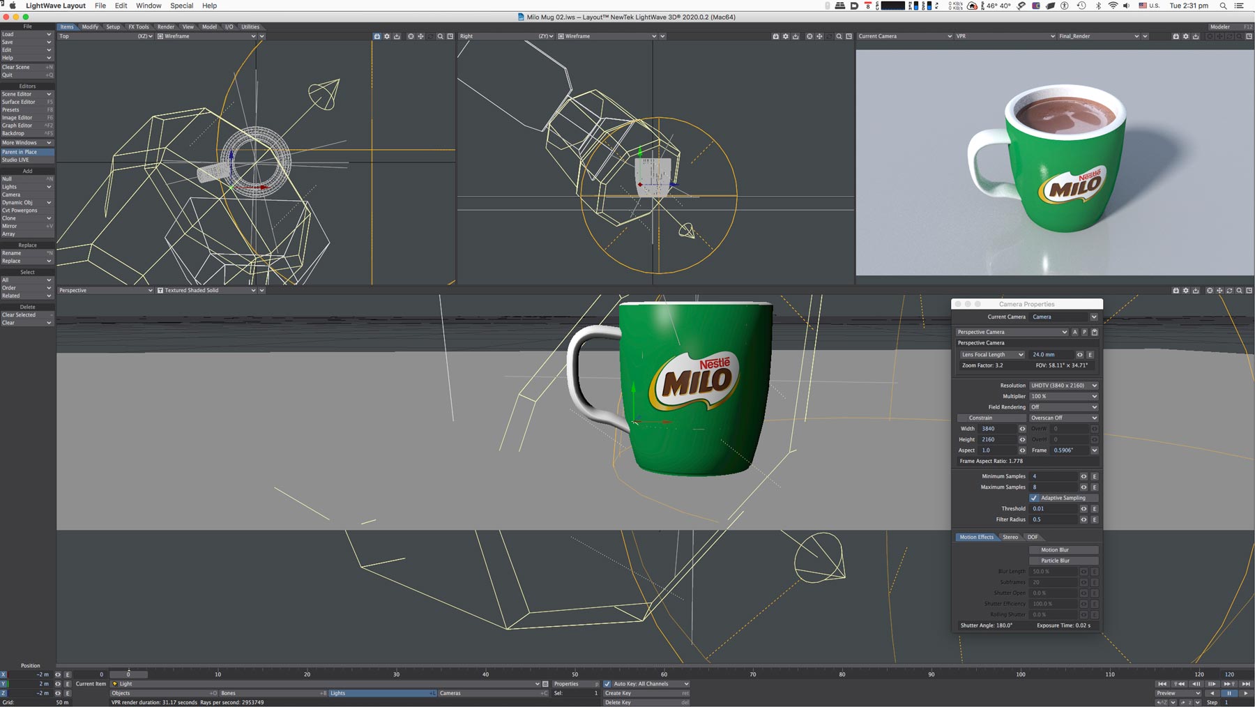
In Lightwave Layout, the virtual camera is positioned for the final render; pointed at the 3D cup as if it was a real camera, pointed at a real cup. Lights are added, shadows and reflections are created. The floating palette is the Camera Properties window. Lights are shown in yellow wireframe. The top right pane is a low resolution camera view; the bottom pane is a perspective view (but not from the camera’s point of view). The camera view will be rendered out as the high resolution final image showing all the detail – see the final rendered image at the top of the page.